
Complex CAD data clearly visualized

Professional CAD Viewer for all 3D formats

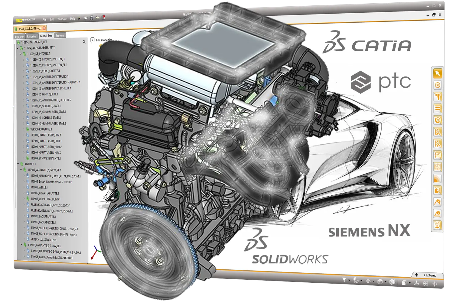
3D_Analyzer is the central platform for professional CAD visualization, precise technical analysis and efficient collaboration throughout the entire product development process.

  • Read 36 major 3D CAD formats
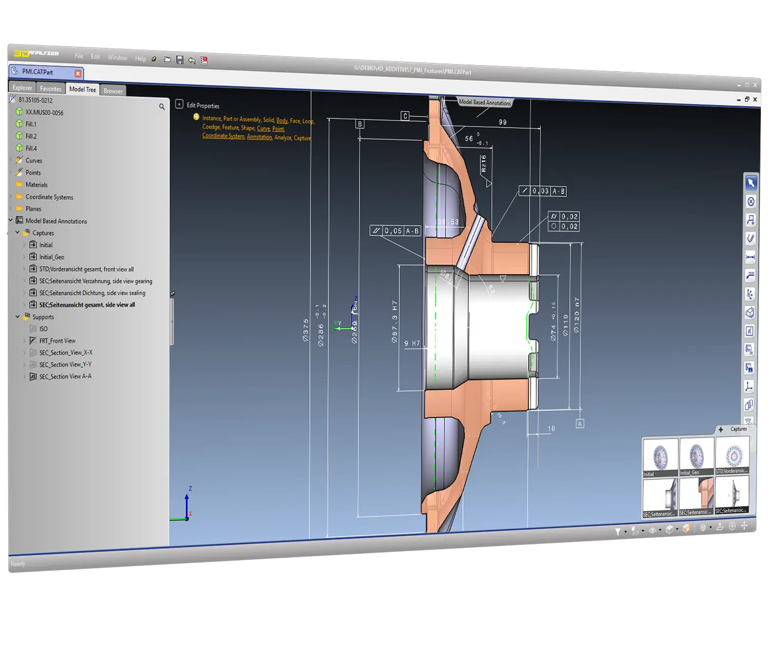
  • Visualization of PMI, design history, and parametric features
  • Perform advanced 3D analyses
  • Measure and create 3D dimensions
  •  Convert CAD data to JT and 3D PDF

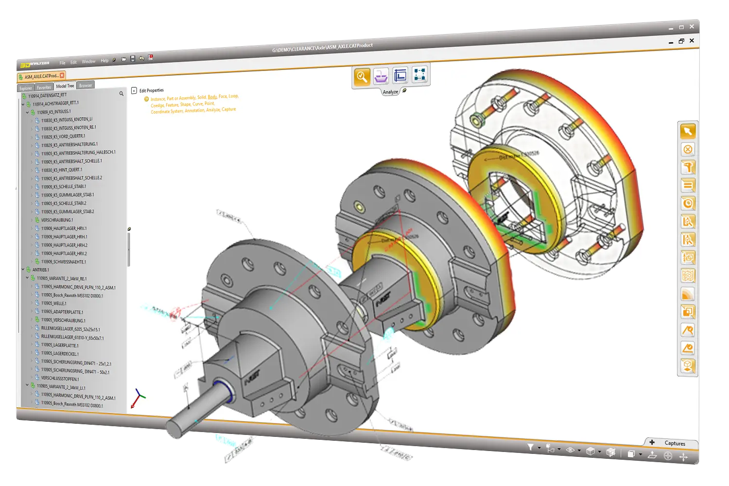
Analysis functions such as model comparison, collision detection, clearance analysis, wall thickness checks and draft angle analysis support reliable design processes, efficient project management and streamlined quotation preparation.

3D_Analyzer is the ideal solution for designers, project managers and everyone who needs to visualize, analyze and communicate CAD data quickly, precisely and securely.

Exact Measures and PMI

The 3D_Analyzer CAD viewer features its own geometry kernel with highly accurate measurement functions based on exact CAD models. As in a native CAD system, users receive precise values, while measurements are not based on approximated, triangulated data as is common in many viewers. In addition, Product Manufacturing Information (PMI) from V5, NX, and Creo, as well as STEP 242 and JT, can be imported.


Dimensions, annotations and section views can be saved and recalled using 3D Master technology. Views and measurements created in 3D_Analyzer can be converted to CT format, JT and PDF, and remain fully functional in interactive 3D PDFs.

Model comparison Detect deviations with precision

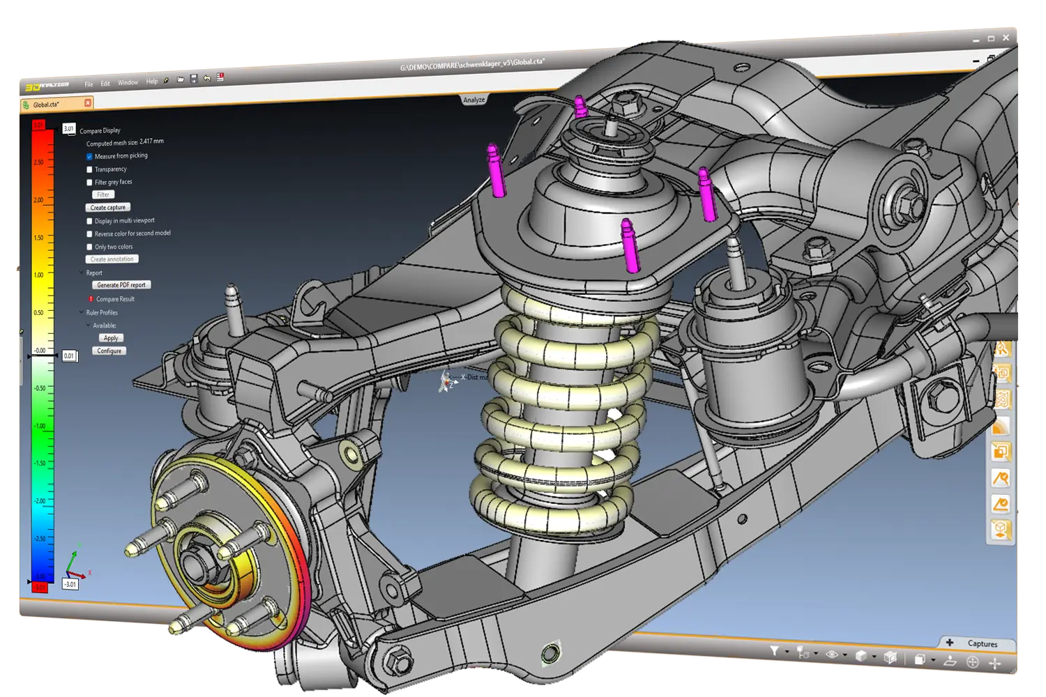
3D_Analyzer compares different versions of 3D CAD models with precision and full traceability, including geometry, assembly structure and product manufacturing information.


Changes, deviations and differences are visually highlighted and can be analyzed directly on the model. This allows users to quickly identify what has changed between two model versions.


Model comparison supports development, quality assurance and project management teams in reliably evaluating changes, detecting potential errors at an early stage and making confident technical decisions.

Create PDF and JT files

With 3D_Analyzer, all major CAD formats such as CATIA V5/V6, NX, SOLIDWORKS, Creo, STEP and JT can be imported and exported to JT and PDF format. Imported product manufacturing information as well as PMI and annotations created in the viewer are preserved.


Analysis results, for example from model comparison or wall thickness checks, can be saved as interactive 3D PDFs and shared with development partners, suppliers and customers.

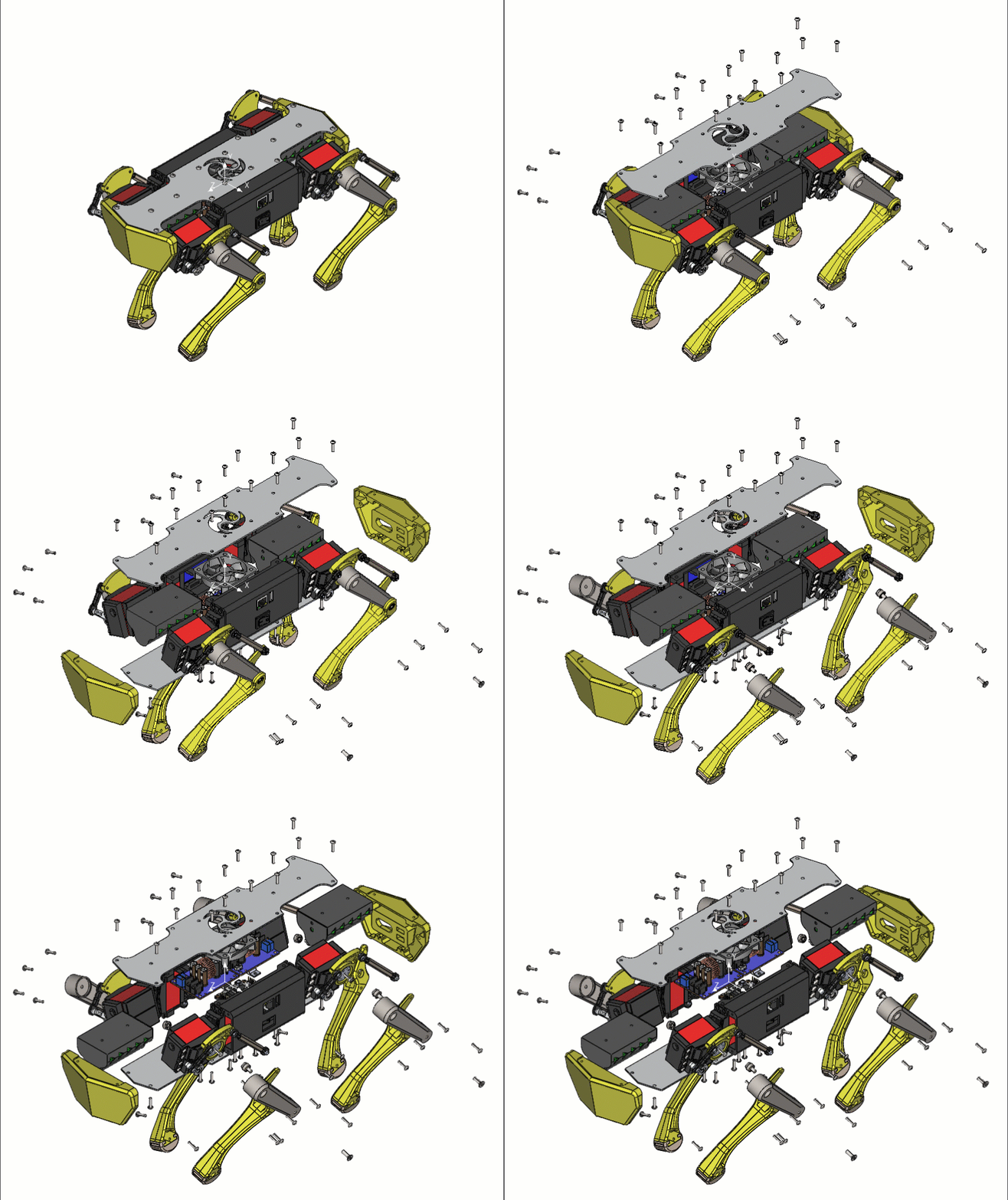
Assembly animation and exploded views

Create animations, motion sequences and exploded views directly on the 3D model to show how components interact within an assembly.


Movements, camera positions, display states and exploded views can be precisely defined and controlled along a timeline. This makes complex assemblies, assembly steps and technical relationships easy to understand.


Ideal for technical reviews, documentation and team collaboration when not only the model itself, but also its structure, function and movement need to be clearly communicated.

Wall thickness analysis

Automatically check the wall thickness of components and detect critical areas directly on the 3D model.

The analysis makes wall thicknesses visually clear through filter functions, adjustable limit values and color-coded display. This allows users to quickly identify areas that require closer evaluation.


For development, quality assurance and manufacturing, this means reduced risk, improved part quality and more reliable decisions before issues lead to costly problems in production, assembly or tooling.

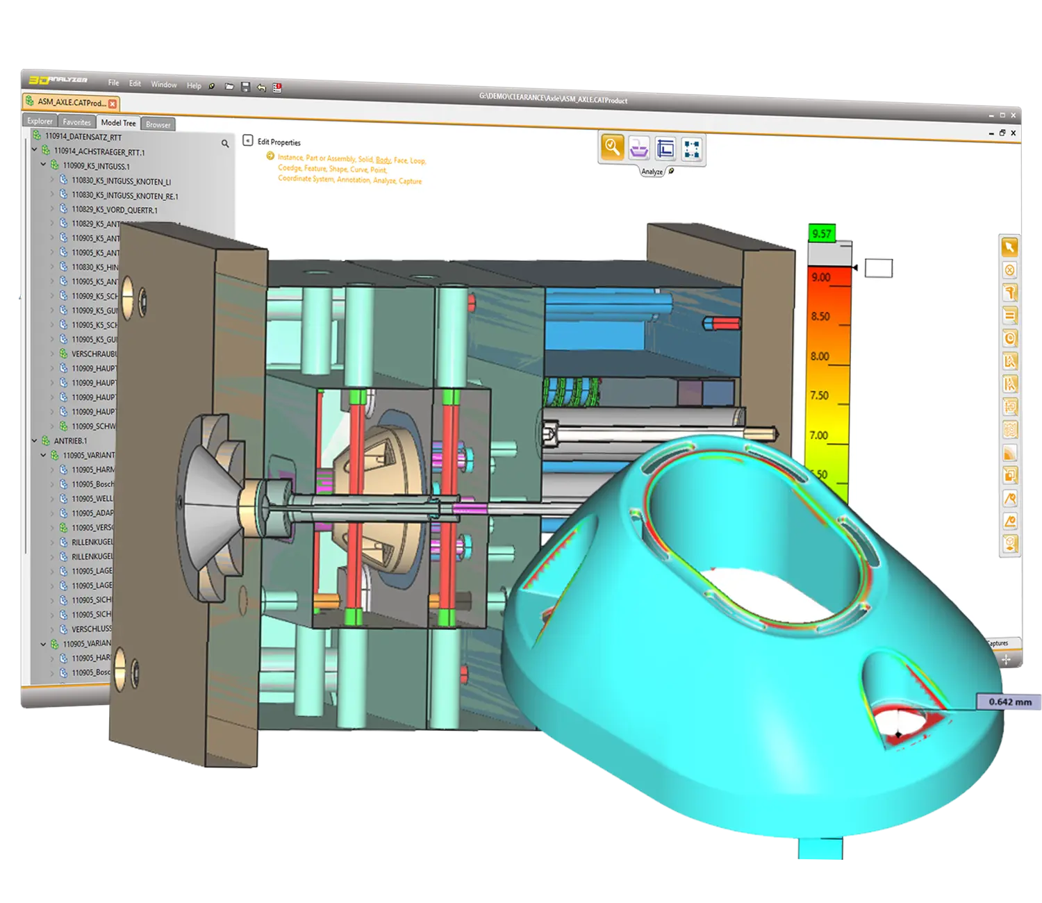
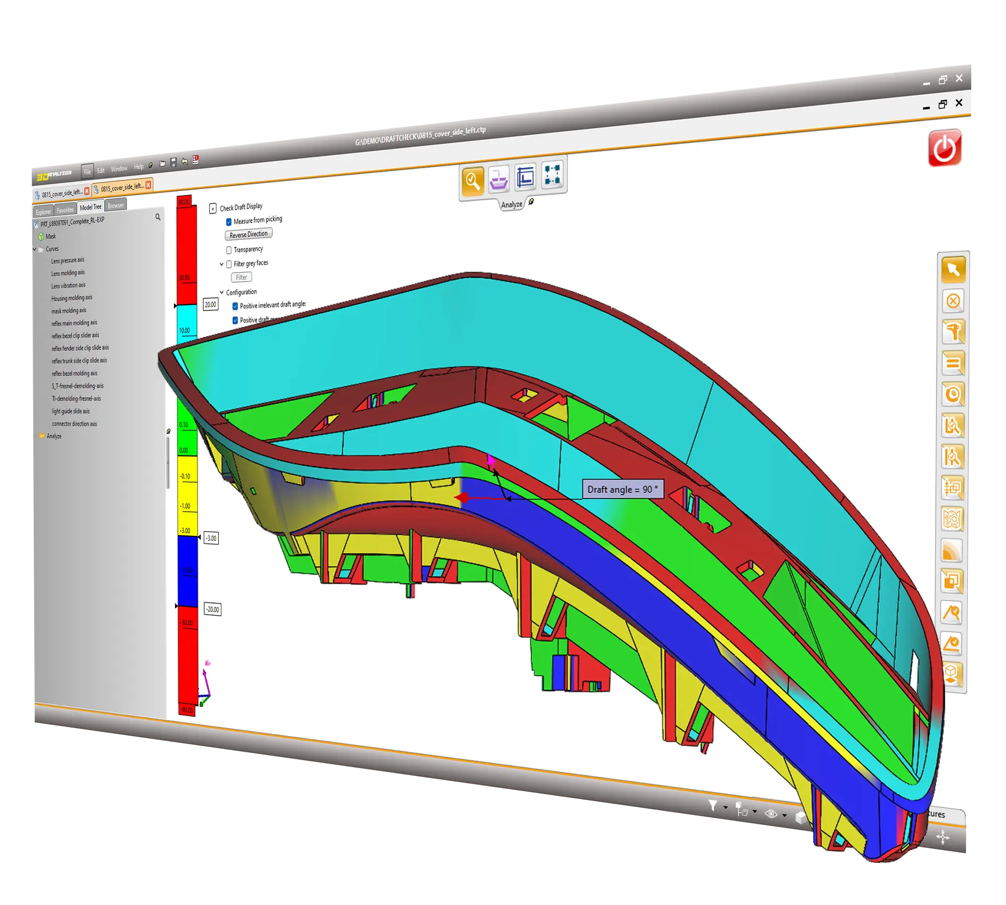
Analysis for tooling and mold making

Special analysis functions allow mold makers to assess manufacturability, tooling concepts and cost implications at an early stage.


Draft angle analysis shows whether surfaces provide sufficient draft and whether a component can be released from the mold without issues. This makes it possible to evaluate whether adjustments to the CAD model are required before the actual tool design begins.


Undercut analysis identifies critical geometries based on a defined demolding direction. Areas that require movable tool elements, such as sliders, are clearly visualized. In addition, a potential mold split can be identified.


The projected area calculation provides the required values for calculating the clamping force of the tool. This allows users to assess at an early stage which machine can be used for production.


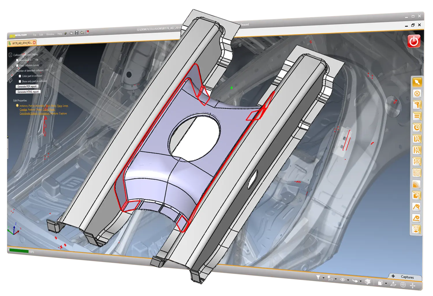
Precise Collision Detection

Automatically check large assemblies for components that touch, overlap or fall below a defined minimum clearance. By using exact CAD models, 3D_Analyzer can reliably distinguish between contact and collision.


Contacts and collisions are displayed directly on the 3D model, clearly highlighted and easy to trace through powerful filter functions.


This enables teams to identify critical areas early, avoid costly rework and make confident decisions before digital errors turn into real costs.

You are currently viewing a placeholder content from YouTube. To access the actual content, click the button below. Please note that doing so will share data with third-party providers.

More Information